
Explore the differences between Asymmetric and Symmetric Integrated Routing and Bridging (IRB) functionality, as tested using SONiC. The packet captures show how each model carries traffic between subnets and which VNI it uses in each direction.
Integrated Routing and Bridging
In the traditional setup of data centers, a central router manages the transfer of data between different subnets. This means data has to travel across the network to this central point and then back out to its destination. However, in a large multi-tenant data center environment this method can lead to inefficient use of bandwidth and sub-optimal forwarding.
To address these issues, EVPN Integrated Routing and Bridging (IRB) provides distributed routing between tenant subnets. RFC 9135 defines its asymmetric and symmetric forwarding models. EVPN IRB combines bridging within a subnet with routing between subnets across the participating VTEPs. IRB seamlessly integrates both routing and bridging functionalities, providing a versatile solution for managing traffic between VLANs and improving the overall efficiency of network communications.
By integrating routing and bridging functionality directly onto the VTEP, the routing operation can occur as close to the end host as possible. By doing this, data can be routed much closer to where it starts and ends, which means it can get to its destination more efficiently.
There are two forwarding models within EVPN for the Integrated Routing and Bridging (IRB) functionality to achieve inter-subnet routing:
- Asymmetric IRB
- Symmetric IRB
Asymmetric IRB
In the asymmetric IRB model, routing and bridging occur at the VXLAN tunnel ingress, with the packet after the routing action being VXLAN bridged to the destination VTEP. The egress VTEP removes the VXLAN header and forwards the packet onto the L2 domain based on the VNI to VLAN mapping. For each destination subnet it routes to, the ingress VTEP needs the corresponding VLAN and L2VNI, plus the destination host's MAC and ARP entry.

Testing in SONiC
For better understanding, Asymmetric Integrated Routing and Bridging (IRB) is tested on SONiC (202311) in GNS3.
The results come from two directly connected virtual switches with no spine. This page explains the forwarding steps and shows the resulting outputs, but does not include the switch configuration.
The lab does not demonstrate hardware forwarding, scale, performance, ARP or ND suppression, failover or a distributed anycast gateway. Before production use, test the design on the intended hardware and SONiC build.

Considering the above figure, Host A wants to communicate with Host B:
1. Since Host B is on a different subnet, Host A sends the frame in VLAN 10 to its gateway which is VTEP 1.
2. VTEP 1 looks up Host B's destination IP in its routing table. It routes the packet into VLAN 20, which maps to Orange VNI 2000.
3. VTEP 1 tunnels the traffic in the Orange VNI (VNI 2000) to VTEP 2.
4. VTEP 2 removes the VXLAN header from the frame, looks up the MAC table and bridges the frame to Host B.
5. Host B wants to send a reply to Host A. Since they are in different subnets, Host B sends the frame in VLAN 20 to its gateway which is VTEP 2.
6. VTEP 2 looks up Host A's destination IP in its routing table. It routes the packet into VLAN 10, which maps to Green VNI 1000.
7. VTEP 2 tunnels the traffic in the Green VNI (VNI 1000) to VTEP 1.
8. VTEP 1 removes the VXLAN header from the frame, looks up the MAC table, and bridges the traffic to Host A.
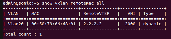
The figure below shows SONiC-1's VXLAN remote MAC table. Its dynamic Vlan20 entry is the MAC address of Host B, learned from VTEP 2.2.2.2 in VNI 2000.
For better understanding, packets are captured with Wireshark. The figure below shows that when Host A sends the traffic to Host B then VTEP1 tunnels the traffic in the VNI 2000 to VTEP2.

The figure below shows that when Host B sends the reply to Host A then VTEP2 tunnels the traffic in the VNI 1000 to VTEP1.

Issue
Each asymmetric IRB VTEP needs the VLANs, L2VNIs and gateway interfaces for every subnet in the tenant VRF, including subnets with no local hosts. It also holds MAC and ARP entries for remote hosts in those subnets, so its forwarding tables grow with the whole tenant rather than with its local hosts.
Symmetric IRB
In symmetric IRB routing, both ingress and egress VTEPs perform IRB routing and bridging. The ingress VTEP routes each packet in the tenant VRF. It then encapsulates the packet with the egress VTEP's router MAC as the inner destination MAC address. In this approach, all routed VXLAN traffic is directed through a dedicated transit VNI known as the L3VNI. This allows bidirectional traffic to traverse on the same VNI in both directions.
Using the L3 VNI associated with each tenant VRF, an ingress VTEP routes all traffic for the prefix to an egress VTEP on the L3 VNI. The egress VTEP routes from the L3 VNI to the destination virtual network or bridge domain. The L3 VNI does not have to be associated with an IP address; routing is set up in the data plane using the egress VTEP's MAC address. This matches the interface-less IP-VRF-to-IP-VRF model in RFC 9136, which FRR uses. The EVPN routes carry the remote VTEP address and router MAC, so no overlay-index lookup is needed. For routed traffic, the ingress VTEP does not need the destination VLAN configured locally, or MAC and ARP entries for remote hosts. It needs the remote route, the egress VTEP address and router MAC, and underlay reachability to that VTEP. For this reason, symmetric IRB scales better when each VTEP hosts only some of the subnets. Asymmetric IRB needs each destination subnet configured on every ingress VTEP.
In the feature comparison at the end of this guide, MAC DA means the inner destination MAC address. The ingress VTEP also needs a route to the destination and underlay reachability to the remote VTEP. The statement that symmetric IRB cannot be deployed in the default VRF is not an EVPN protocol rule. This SONiC lab places tenant routing in Vrf-Green.
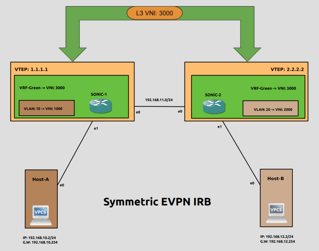
Considering the above figure Host A wants to communicate with Host B:
- Because the destination is in a different subnet from Host A, Host A sends the frame to its gateway, VTEP 1 in VLAN 10.
- VTEP 1 looks up the routing table and routes the traffic to the L3VNI and destination VTEP 2.
- VTEP 1 encapsulates the packet in L3VNI 3000. The outer destination IP is VTEP 2's address, and the inner destination MAC is VTEP 2's router MAC.
- VTEP 2 decapsulates the traffic and routes traffic to the destination VLAN.
- VTEP 2 bridges traffic towards Host B.
- The return traffic is routed similarly using the same L3VNI.
The figure below shows the router MAC of remote VTEP 2.2.2.2 in Vlan30 and VNI 3000. In this topology, the remote VTEP is SONiC-2.

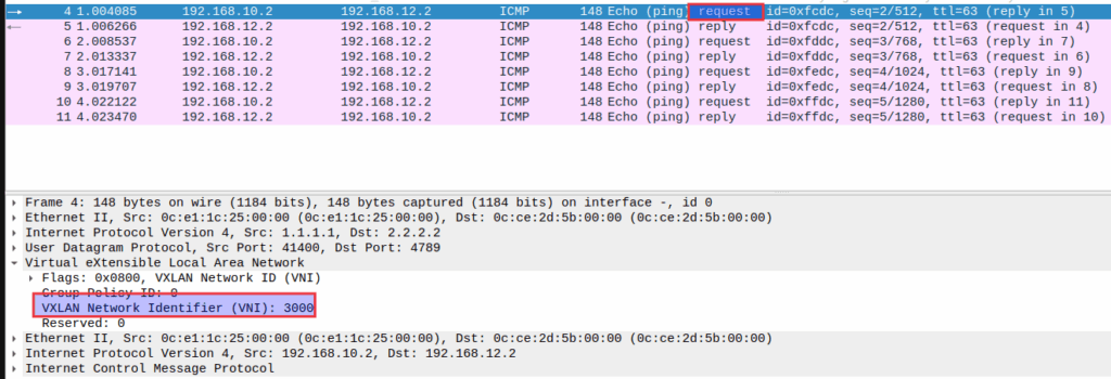
For better understanding, packets are captured with Wireshark. The figure below shows that when Host A sends the traffic to Host B then VTEP1 tunnels the traffic in the L3VNI 3000 to VTEP2.
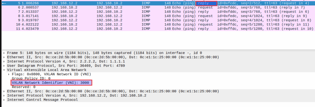
The figure below shows that when Host B sends the reply to Host A then VTEP2 tunnels the traffic in the same L3VNI 3000 to VTEP1.
Symmetric and Asymmetric IRB Feature Comparison

References
About Hardware Nation:
Hardware Nation is a professional services company that accelerates network transformation through a disaggregated, open approach, enabling freedom of choice, flexibility, and cost efficiency. Our seasoned experts have worked on projects for some of the world’s leading organizations, leveraging a hybrid cloud-first and AI-enabled approach. We help our customers navigate the ecosystem, drawing on decades of experience. Our deployments are powered by leading white box and OEM network, compute, and storage vendors. Our expertise encompasses a wide range of industries and use cases, including enterprise, cloud, data center, AI, 5G/ISP infrastructure, and edge IT.
Humza Altaf
Network Engineer
Humza is a network engineer at Hardware Nation Labs, where his enthusiasm for Open Networking drives his work. With a blend of deep expertise and innovative approaches, he designs robust, scalable networks of the future. His practical experience includes configuring and deploying a range of protocols such as LACP, VLANs, MPLS, and VRRP. At his previous role, he was part of a SONiC testing team, further honing his skills in network setup and troubleshooting. Humza is also adept at network analysis with tools like Wireshark, enhancing his ability to manage complex network environments.