

Multi-chassis link aggregation (MCLAG) lets a server or downstream switch form one PortChannel across two peer switches. Use it when a device needs connections to both peers and must keep a path available if one fails.
SONiC’s ICCPd is a lightweight implementation based on ICCP, the Inter-Chassis Communication Protocol (RFC 7275). ICCPd runs over TCP port 8888, so it does not interoperate with standard RFC 7275 ICCP, which runs over LDP. In this lab, S1 and S2 form the MCLAG pair, with S3 and S4 connected to both.
This guide follows the GNS3 lab published by Humza Altaf, SONiC Network Engineer, in October 2023. The lab outputs shown here come from that work, and the original guide is available to download.
The Lab Topology
Four SONiC virtual switches, known as sonic-vs, and two VPCS hosts run in GNS3. No physical switch hardware was used. The original lab did not record the SONiC build or image version.
| Connection | PortChannel | VLAN membership |
|---|---|---|
| S1 to S2 | PortChannel0008 | VLAN 100 tagged |
| S3 to S1 and S2 | PortChannel0010 | VLAN 100 tagged |
| S4 to S1 and S2 | PortChannel0009 | VLAN 100 tagged |
| PC1 to S3 | None | VLAN 100 untagged |
| PC2 to S4 | None | VLAN 100 untagged |
S1 and S2 form MCLAG domain 100. Use the following addresses.
| Device | Interface | Address |
|---|---|---|
| S1 | Vlan100 | 192.168.100.1/24 |
| S2 | Vlan100 | 192.168.100.2/24 |
| PC1 | Host interface | 192.168.100.4/24 |
| PC2 | Host interface | 192.168.100.3/24 |
Map the Interfaces
GNS3 and SONiC use different interface numbers in this lab. Match each link to the SONiC name before entering the commands.
| GNS3 interface | SONiC interface |
|---|---|
| Ethernet 0 | Ethernet0 |
| Ethernet 1 | Ethernet4 |
| Ethernet 2 | Ethernet8 |
| Ethernet 3 | Ethernet12 |
| Link | Side A (SONiC name) | Side B (SONiC name) |
|---|---|---|
| S1 to S2, first member | S1 Ethernet0 | S2 Ethernet0 |
| S1 to S2, second member | S1 Ethernet4 | S2 Ethernet4 |
| S1 to S3 | S1 Ethernet8 | S3 Ethernet0 |
| S2 to S3 | S2 Ethernet8 | S3 Ethernet4 |
| S1 to S4 | S1 Ethernet12 | S4 Ethernet0 |
| S2 to S4 | S2 Ethernet12 | S4 Ethernet4 |
| S3 to PC1 | S3 Ethernet8 | PC1 e0 |
| S4 to PC2 | S4 Ethernet8 | PC2 e0 |
Configure S1 first. S2 follows in step 7, then S3, S4 and the hosts.
Step 1. Enable ICCPd
Before enabling ICCPd, check that its feature is listed. If iccpd is not listed, use a SONiC image that includes ICCPd.
show feature status iccpdEnable the feature and save the configuration. Then check that the container is running.
sudo config feature state iccpd enabled
sudo config save -y
docker ps
You should see an iccpd entry with an Up status, as in the example below. The uptime will vary.
IMAGE                 STATUS          NAMES
docker-iccpd:latest    Up 15 seconds   iccpd
The 2023 lab used systemctl unmask and systemctl start. Those commands do not save the enabled feature state for the next boot. The feature state command, followed by config save, does.
Step 2. Remove the Existing Interface Addresses
Remove any IP addresses on Ethernet0, Ethernet4, Ethernet8 and Ethernet12, which will join the PortChannels. Start by listing the configured addresses.
show ip interfacesThe output below is cut short and shows only Ethernet0 and Ethernet4. The lab also removed an address from Ethernet8. Use the values from your own switch when removing addresses.
Expected output
Interface    Master    IPv4 address/mask    Admin/Oper    BGP Neighbor    Neighbor IP
-----------  --------  -------------------  ------------  --------------  -------------
Ethernet0              10.0.0.0/31          up/up         ARISTA01T2      10.0.0.1
Ethernet4              10.0.0.2/31          up/up         ARISTA02T2      10.0.0.3
Remove the lab addresses with these commands. If Ethernet12 also has an address, remove it the same way using the prefix your switch shows.
sudo config interface ip remove Ethernet0 10.0.0.0/31
sudo config interface ip remove Ethernet4 10.0.0.2/31
sudo config interface ip remove Ethernet8 10.0.0.4/31
Run the address check again and confirm that none of these four interfaces has a remaining IP address. Save the configuration before adding the PortChannels.
show ip interfaces
sudo config save -y
Step 3. Create the PortChannels
List any existing PortChannels before creating new ones. In this lab, the initial listing has no entries.
show interfaces portchannelCreate the three PortChannels on S1. PortChannel0008 connects the peers, while PortChannel0010 and PortChannel0009 connect to S3 and S4.
sudo config portchannel add PortChannel0008
sudo config portchannel add PortChannel0009
sudo config portchannel add PortChannel0010
You can add --fast-rate true when creating a PortChannel for faster LACP failure detection. The commands above leave LACP at its default slow rate.
| PortChannel on each MCLAG peer | Member interfaces |
|---|---|
| PortChannel0008 | Ethernet0, Ethernet4 |
| PortChannel0010 | Ethernet8 |
| PortChannel0009 | Ethernet12 |
Step 4. Add the Member Interfaces
Add the physical interfaces to their PortChannels. Then check the PortChannels with the second command.
sudo config portchannel member add PortChannel0008 Ethernet0
sudo config portchannel member add PortChannel0008 Ethernet4
sudo config portchannel member add PortChannel0010 Ethernet8
sudo config portchannel member add PortChannel0009 Ethernet12
show interfaces portchannelThese PortChannels remain down until the far ends are configured. After completing S2, S3 and S4, you should see the output below on S1. Members marked S are selected.
Expected output
No.   Team Dev         Protocol       Ports
0008  PortChannel0008  LACP(A)(Up)    Ethernet4(S) Ethernet0(S)
0009  PortChannel0009  LACP(A)(Up)    Ethernet12(S)
0010  PortChannel0010  LACP(A)(Up)    Ethernet8(S)
Step 5. Create VLAN 100
Check the VLAN table, then create VLAN 100. The initial table is empty in this lab.
show vlan briefsudo config vlan add 100Add VLAN 100 as tagged on all three PortChannels. Configure both MCLAG peers with the same membership.
sudo config vlan member add 100 PortChannel0008
sudo config vlan member add 100 PortChannel0009
sudo config vlan member add 100 PortChannel0010
Step 6. Configure the MCLAG Domain
Set domain 100, the local and peer addresses, and the peer link on S1. Each peer needs its own Vlan100 address for the ICCP session, so enable unique-ip on that interface.
Add the domain before enabling unique-ip, then assign the Vlan100 address. The MCLAG CLI rejects unique-ip if no domain exists or if Vlan100 already has an IP address. Add the two client PortChannels as MCLAG members.
sudo config mclag add 100 192.168.100.1 192.168.100.2 PortChannel0008
sudo config mclag unique-ip add Vlan100
sudo config mclag member add 100 PortChannel0009
sudo config mclag member add 100 PortChannel0010
Assign the address to Vlan100 and check the VLAN table. All three PortChannels should be tagged in VLAN 100. Save S1’s completed configuration.
sudo config interface ip add Vlan100 192.168.100.1/24
show vlan brief
sudo config save -y
Summary of show vlan brief
| VLAN ID | IP address | Member | Port tagging | Proxy ARP |
|---|---|---|---|---|
| 100 | 192.168.100.1/24 | PortChannel0008 | tagged | disabled |
| 100 | 192.168.100.1/24 | PortChannel0009 | tagged | disabled |
| 100 | 192.168.100.1/24 | PortChannel0010 | tagged | disabled |
ICCP and the Peer Link
In this lab, the ICCP session uses Vlan100 and crosses PortChannel0008. S3 and S4 do not send a frame back out the PortChannel it arrived on, so their uplinks provide no alternate path between the peers.
If PortChannel0008 fails while both peers remain up, the ICCP session drops too. S2 then returns to its own LACP system ID, so S3 and S4 deselect their links to S2 and send traffic to S1. Both peers remove MAC entries that point to the failed peer link. A device in VLAN 100 connected only to S2, with no other path, loses access to S1, S3 and S4. The SONiC design describes this behavior. The lab did not test it. In production, use a separate routed link for the MCLAG local and peer IPs, or loopbacks reachable over a path that avoids the peer link.
Step 7. Configure S2
Enable ICCPd on S2 and check its interface addresses. Use the same commands as in step 1.
show feature status iccpd
sudo config feature state iccpd enabled
sudo config save -y
docker ps
show ip interfaces
Remove any routed addresses from Ethernet0, Ethernet4, Ethernet8 and Ethernet12 using the method in step 2. Use S2’s own addresses when removing them, then configure the second peer.
sudo config portchannel add PortChannel0008
sudo config portchannel add PortChannel0009
sudo config portchannel add PortChannel0010
sudo config portchannel member add PortChannel0008 Ethernet0
sudo config portchannel member add PortChannel0008 Ethernet4
sudo config portchannel member add PortChannel0010 Ethernet8
sudo config portchannel member add PortChannel0009 Ethernet12
sudo config vlan add 100
sudo config vlan member add 100 PortChannel0008
sudo config vlan member add 100 PortChannel0009
sudo config vlan member add 100 PortChannel0010
sudo config mclag add 100 192.168.100.2 192.168.100.1 PortChannel0008
sudo config mclag unique-ip add Vlan100
sudo config mclag member add 100 PortChannel0009
sudo config mclag member add 100 PortChannel0010
sudo config interface ip add Vlan100 192.168.100.2/24
sudo config save -y
show interfaces portchannel
show vlan brief
Expect the same PortChannel members and tagged VLAN membership as on S1. S2’s MCLAG settings must match this table.
| S2 setting | Value |
|---|---|
| Vlan100 address | 192.168.100.2/24 |
| MCLAG local IP | 192.168.100.2 |
| MCLAG peer IP | 192.168.100.1 |
| Domain ID | 100 |
| Peer link | PortChannel0008 |
| MCLAG members | PortChannel0009, PortChannel0010 |
Step 8. Configure S3 and S4
On S3, PortChannel0010 contains the links to S1 and S2. On S4, PortChannel0009 contains its links to S1 and S2.
The 2023 lab gave the S3 and S4 results but not the commands, so the commands below come from the SONiC command reference. Each client PortChannel carries tagged VLAN 100, while Ethernet8 connects to the local PC and is untagged.
On each client switch, list the interface addresses first. Remove any routed addresses from Ethernet0, Ethernet4 and Ethernet8 before adding the PortChannel or VLAN membership.
show ip interfacesUse the following removal command for each assigned address. Replace the placeholders with the interface and prefix shown on that switch.
sudo config interface ip remove <interface_name> <ip_addr>S3
Create PortChannel0010 and add its two uplinks. Then add VLAN 100, with Ethernet8 untagged.
sudo config portchannel add PortChannel0010
sudo config portchannel member add PortChannel0010 Ethernet0
sudo config portchannel member add PortChannel0010 Ethernet4
sudo config vlan add 100
sudo config vlan member add 100 PortChannel0010
sudo config vlan member add -u 100 Ethernet8
sudo config save -y
S4
Create PortChannel0009 and add its two uplinks. Configure VLAN 100 and Ethernet8 as on S3.
sudo config portchannel add PortChannel0009
sudo config portchannel member add PortChannel0009 Ethernet0
sudo config portchannel member add PortChannel0009 Ethernet4
sudo config vlan add 100
sudo config vlan member add 100 PortChannel0009
sudo config vlan member add -u 100 Ethernet8
sudo config save -y
Check both switches with the following commands. Compare the PortChannel members and VLAN tagging with the tables below.
show interfaces portchannel
show vlan brief
Expected output
| Switch | PortChannel | Protocol and state | Members |
|---|---|---|---|
| S3 | PortChannel0010 | LACP(A)(Up) | Ethernet4(S), Ethernet0(S) |
| S4 | PortChannel0009 | LACP(A)(Up) | Ethernet4(S), Ethernet0(S) |
Summary of show vlan brief
| Switch | VLAN ID | Member | Port tagging | Proxy ARP |
|---|---|---|---|---|
| S3 | 100 | Ethernet8 | untagged | disabled |
| S3 | 100 | PortChannel0010 | tagged | disabled |
| S4 | 100 | Ethernet8 | untagged | disabled |
| S4 | 100 | PortChannel0009 | tagged | disabled |
Step 9. Check the MCLAG State
Inspect domain 100 on S2. Confirm that the keepalive is OK and synchronization is completed.
mclagdctl -i 100 dump stateExpected output
The MCLAG's keepalive is: OK
MCLAG info sync is: completed
Domain id: 100
Local Ip: 192.168.100.2
Peer Ip: 192.168.100.1
Peer Link Interface: PortChannel0008
Keepalive time: 1
sesssion Timeout : 15
Peer Link Mac: 0c:27:3a:e4:00:00
Role: Standby
MCLAG Interface: PortChannel0009,PortChannel0010
Loglevel: NOTICE
The keepalive and synchronization lines show a healthy session when they read keepalive is: OK and info sync is: completed. The role line can appear even when the session is down. Standby is a control-plane role. Both peers forward traffic.
Step 10. Configure the Hosts
Configure PC1 and PC2 with the addresses below. The original lab entered the subnet mask as the gateway. The commands below correct that.
PC1
ip 192.168.100.4/24
show ip
PC2
ip 192.168.100.3/24
show ip
You should see the following IP/MASK values. These commands do not set a gateway.
Expected values
| Host | IP/MASK |
|---|---|
| PC1 | 192.168.100.4/24 |
| PC2 | 192.168.100.3/24 |
What the Lab Showed
PC1 pinged PC2 at 192.168.100.3 and got replies with TTL 64.
ping 192.168.100.3Lab output
84 bytes from 192.168.100.3 icmp_seq=1 ttl=64 time=2.485 ms
84 bytes from 192.168.100.3 icmp_seq=2 ttl=64 time=2.676 ms
84 bytes from 192.168.100.3 icmp_seq=3 ttl=64 time=2.750 ms
84 bytes from 192.168.100.3 icmp_seq=4 ttl=64 time=2.649 ms
84 bytes from 192.168.100.3 icmp_seq=5 ttl=64 time=2.699 ms
With the S1 to S4 link paused, PC1 still reached PC2. S4 kept its link to S2, but with LACP at its slow rate the traffic may simply have been using that link already, so this does not show LACP detecting the failure.
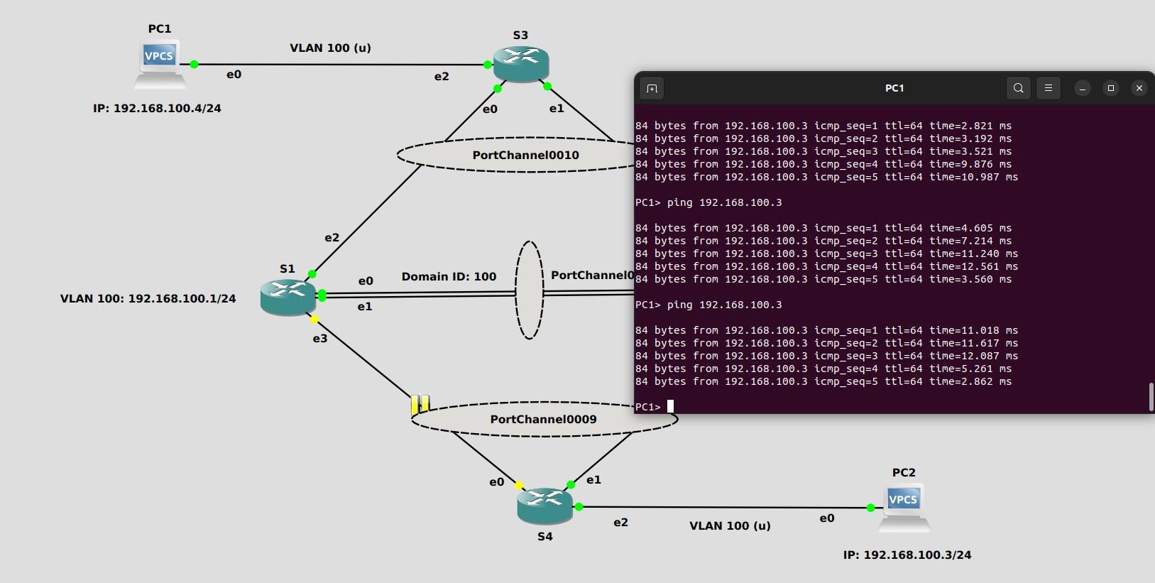
With S1 stopped, pings failed at first and recovered after a few seconds. The ping runs were short, so they do not measure failover time.
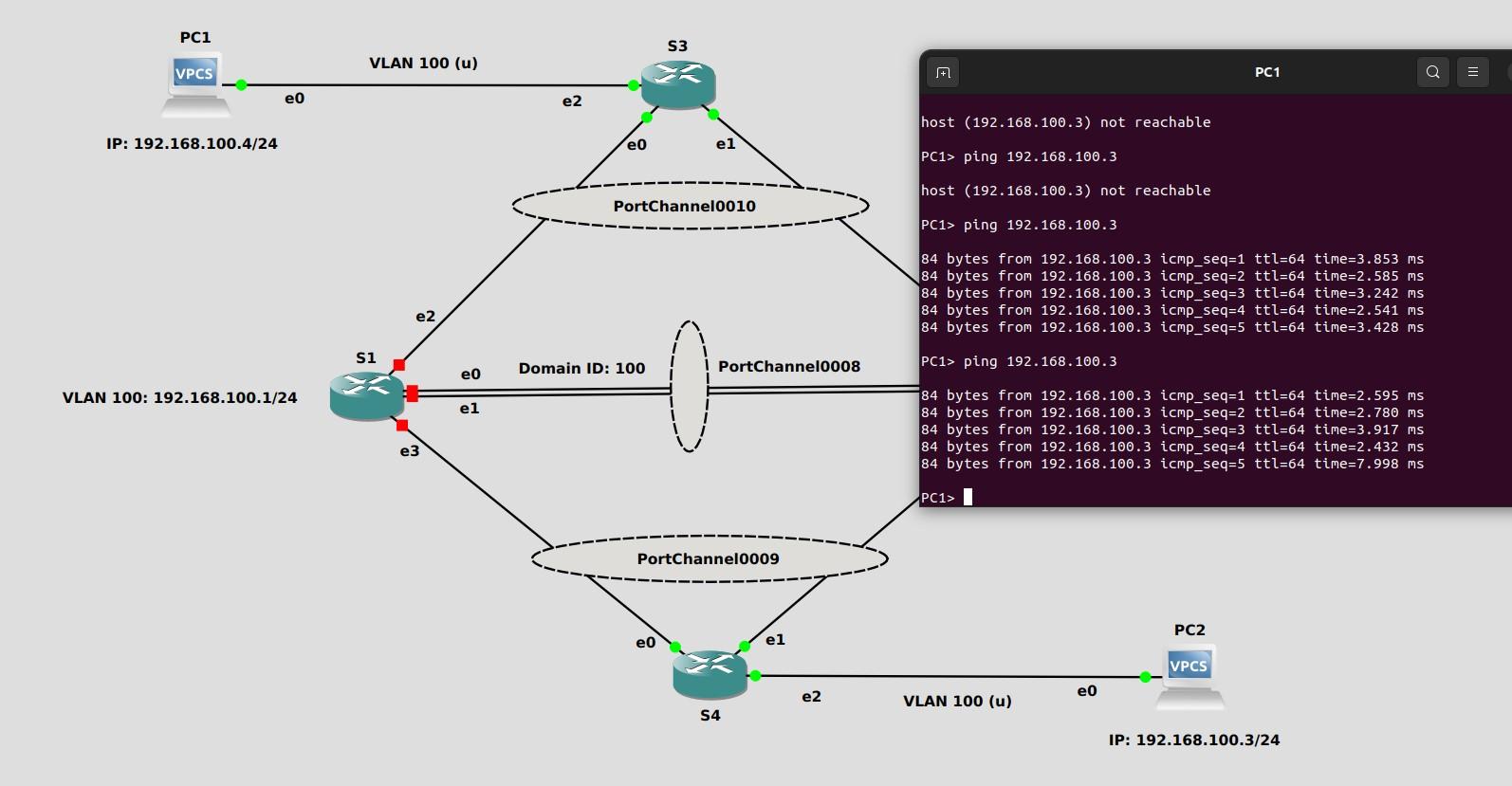
Pausing a link or stopping a node in GNS3 can leave the carrier up on the neighboring switch, so LACP has to notice that LACPDUs stopped arriving. At the default slow rate this takes longer than detecting a lost physical link, so these results are not failover times for real switches.
MCLAG Support Depends on the SONiC You Run
This lab uses community SONiC on a virtual switch. On hardware, whether you get MCLAG, and which MCLAG features, depends mainly on which SONiC distribution and release you run, such as community SONiC, a switch vendor's own distribution or Broadcom's Enterprise SONiC. Broadcom licenses Enterprise SONiC per switch in Base and Advanced packages. Public sources disagree on which package includes MCLAG, so confirm it with the vendor.
The chip still matters for the wider feature set. In our conversations with switch vendors, one vendor's engineer told us that Trident chips are generally more feature rich because they are designed for leaf roles, while Tomahawk chips suit spine and super spine roles. For a deployment on Broadcom Enterprise SONiC that needed MCLAG, the same vendor recommended a Trident 4 switch with 32 ports at 400G. Its own SONiC distribution, release 202311.4, lists MCLAG on all of its 400G and 800G switches, including those built on Tomahawk 3, 4 and 5. Before ordering, ask the switch vendor to confirm the chip, the SONiC distribution, release and package, and support for L2 or L3 MCLAG alongside the other features you need.
Before Using MCLAG in Production
Check the keepalive, synchronization, PortChannel members and VLAN tagging, then test traffic between the hosts. Use a path for the ICCP session that does not depend on the peer link.
On your own hardware and SONiC release, test peer-link failure, the loss of a peer and an ICCPd restart, and measure the interruption. Verify that traffic and peer synchronization recover after each test.

Humza Altaf
Hardware Nation


